Scope of delivery
| Parameter | Value | ||||||||||
| Model | BE42 | ||||||||||
| Weight | 287 g (incl. batteries) | ||||||||||
| Dimensions (length x width x height) |
217 x 80 x 38 mm | ||||||||||
| Max. diameter of conductor | approx. 28 mm | ||||||||||
| Display | LSC (2000 counts) | ||||||||||
| Measuring rate | 2 per second | ||||||||||
| Input resistance (V AC and V DC) | 10 MΩ | ||||||||||
| Max. input value alternating current | 400 A | ||||||||||
| Max. input value voltage (AC and DC) | 600 V AC/DC | ||||||||||
| Max. input value resistance, diode, continuity | 250 V AC/DC | ||||||||||
| Frequency range alternating current | 50/60 Hz (AAC) | ||||||||||
| Frequency range AC voltage | 50–400 Hz (VAC) | ||||||||||
| Ambient conditions | 5°C to 40°C (41°F to 104°F) | ||||||||||
| Storage conditions | -20°C to 60°C (-4°F to 140°F) | ||||||||||
| Relative humidity | max. 80 % RH at 31 °C (87 °F), decreasing linearly up to 50 % RH at 40 °C (104 °F) |
||||||||||
| Type of protection | IP20 | ||||||||||
| Batteries | 2 x 1.5 V AAA | ||||||||||
| Overvoltage protection | Category lll 600 V | ||||||||||
| Automatic switch-off | after 15 minutes | ||||||||||
|
|||||||||||
| Function | Range | ||||||||||
| Diode measurement | Test voltage: approx. 2.5 V Test current: approx. 0.6 mA | ||||||||||
| Continuity check | Acoustic signal at ≤ 100 Ω Acoustic signal possible at 20 Ω – 150 Ω No acoustic signal at > 150 Ω |
||||||||||
| Measuring range | Resolution | Accuracy | Measuring range exceeded | ||
| AC voltage (V/AC) | |||||
| 2 V | 1 mV | ± (1.8 % + 8 digits) |
OL will be indicated on the display. | ||
| 20 V | 10 mV | ||||
| 200 V | 0.1 V | ||||
| 600 V | 1 V | ± (2.5 % + 8 digits) |
|||
| DC voltage (V/DC) | |||||
| 200 mV | 1 mV | ± (0.8 % + 4 digits) |
OL will be indicated on the display. | ||
| 2 V | 10 mV | ± (1.5 % + 2 digits) |
|||
| 20 V | 0.1 V | ||||
| 200 V | 1 V | ||||
| 600 V | 1 V | ± (2.0 % + 2 digits) |
|||
| Alternating current (A/AC) | |||||
| 2 A | 0.01 A | ± (2.5 % + 10 digits) |
OL will be indicated on the display. | ||
| 20 A | 0.1 A | ± (2.5 % + 4 digits) |
|||
| 200 A | 1 A | ± (2.5 % + 4 digits) |
|||
| 400 A | 1 A | ± (3 % + 6 digits) |
|||
| Resistance(Ω) | |||||
| 200 Ω | 0.1 Ω | ± (1.0 % + 4 digits) |
OL will be indicated on the display. | ||
| 2 kΩ | 1 Ω | ± (1.5 % + 2 digits) |
|||
| 20 kΩ | 10 Ω | ||||
| 200 kΩ | 100 Ω | ||||
| 2 MΩ | 1 kΩ | ± (2.5 % + 3 digits) |
|||
| 20 MΩ | 10 kΩ | ± (3.5 % + 5 digits) |
|||
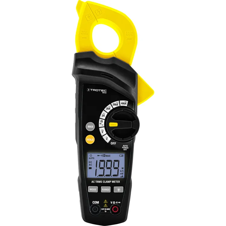
The compact BE42 True RMS current clamp with integrated flashlight enables highly precise, non-contact measurement of AC current as well as AC/DC voltage in industrial, building services and electrical installations – even in tight control cabinets and hard-to-reach places. Current is measured safely and contact-free via the electromagnetic field, without interrupting the circuit or disconnecting cables, making testing and maintenance work faster, safer and more efficient. Thanks to the automatic power-off function, the device also saves energy when not in use.
With its comprehensive professional features, the BE42 far surpasses conventional multimeters. It measures AC/DC voltage, AC current, resistance and performs continuity tests on cables, fuses and contacts. Practical functions such as HOLD, MAX display, battery status indicator, overload warning and integrated LED work light make daily work much easier. All measured values are clearly shown on the backlit LCD display, and the measuring function is conveniently selected via the rotary switch.
Designed for comfortable one-handed operation, the ergonomically optimised BE42 impresses with a slim, wide-opening clamp and a compact, shock-protected housing with non-slip rubber coating (IP40). The device meets all safety requirements of measurement category CAT III 600 V and is designed for current measurements up to 400 A – combining maximum safety, precision and robustness at an excellent price-performance ratio.
Conventional measuring devices assume that an AC signal is perfectly sinusoidal and calculate the displayed value based on this assumption. In reality, however, modern electrical consumers such as switching power supplies, frequency converters or speed controllers generate distorted, non-sinusoidal waveforms. Because of this, conventional measuring devices often display incorrect values.
True RMS measuring instruments, on the other hand, can accurately measure both sinusoidal and non-sinusoidal signals and determine the true effective (RMS) value of any alternating quantity. “True Root Mean Square” stands for the correct calculation and output of the true RMS value – ensuring precise, reliable measurement results even under real-world conditions.


Reviews
There are no reviews yet.